
TOOL DEVELOPMENT & MANUFACTURE / HW6368
Rear bracket die casting tool
Quality checks across tooling and trials.
The customer specified porosity limits for critical areas of the rear bracket. This two-cavity project shows our tooling scope and how mold-base measurements, assembly checks and T0 sample observations support engineering review.
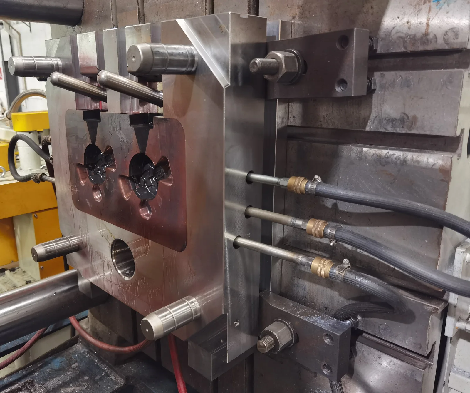
Aluminium alloy
Two cavities
8418 tool steel
Tool inspection & T0 trial
The quality requirement
Beyond support and assembly location, internal quality in critical areas matters.
The rear bracket provides support and assembly location. The customer defined porosity requirements by area, with the following limits for critical areas.
- Pore density
- ≤ 1 pore / 3 mm²
- Maximum pore diameter
- ≤ 0.5 mm
These are inspection requirements, not measured results reported on this page.
Our tooling scope
Our scope covered engineering review, DFM and mold-flow analysis, tool design and manufacture, trials, modification and inspection. The cavity and core inserts use 8418 tool steel. The following sections examine the project’s quality work at two levels: the tool itself and the T0 trial.
Inspecting the tool
Tool dimensions, fits and movement are an important part of quality review.
The mold-base inspection record pairs design dimensions with measured values. The tooling checklist covers the mold base, inserts, components and assembly—from plates and holes to parting surfaces, cooling circuits, die-closing guides and ejector components.
- Mold base
- Overall dimensions, clamping slots, holes, guide fits and cooling-port identification.
- Die inserts
- Parting and cavity surfaces, water-circuit continuity, ejector-pin fits and insert assembly codes.
- Components and standard parts
- Screw lengths, cooling-pipe assembly, and identification of spare insert pins and ejector pins.
- Assembly
- Die closing and guide fits, ejector-component positions, movement of fitted parts and lock-plate assembly.
View selected mold-base measurements
| Part | Required (mm) | Measured (mm) |
|---|---|---|
| A plate | 540 × 520 × 146.8 | 540.08 × 520.06 × 146.84 |
| B plate | 540 × 520 × 139.8 | 540.09 × 520.08 × 139.83 |
| Support block | 480 × 120 × 110 | 480.06 × 120.07 × 110.04 |
This extract presents design requirements and measurements without a tolerance-conformance assessment.
Evaluating the T0 trial
Read the tooling setup, die-surface temperatures and sample observations together.
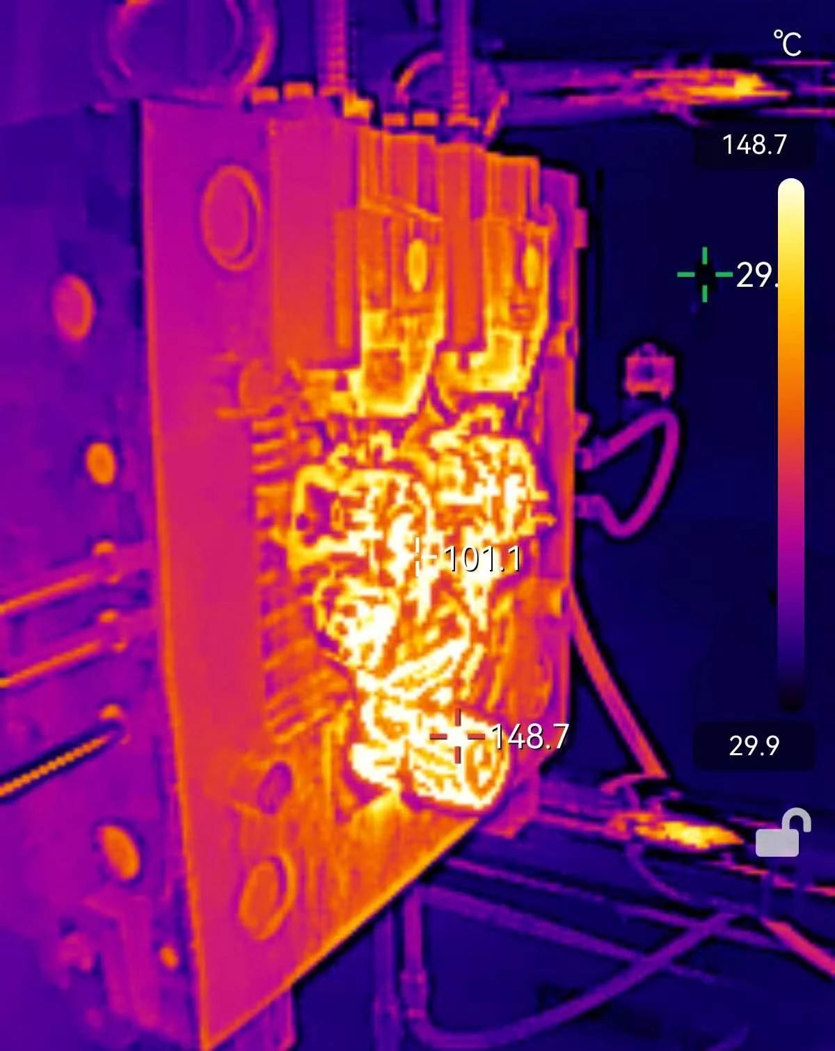
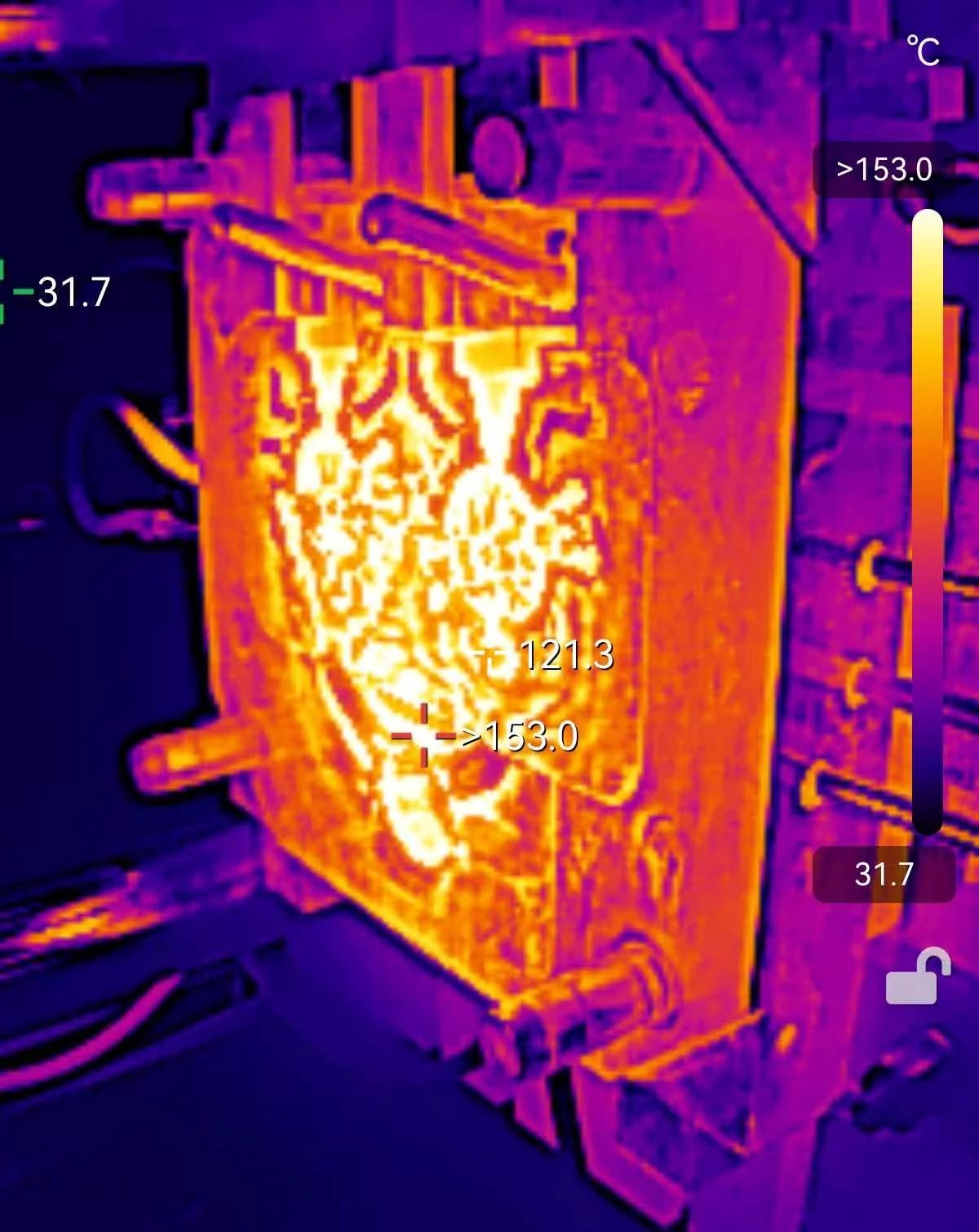
The T0 records include cooling-water inlet and outlet connections for the fixed and moving die halves, thermal images after spraying and samples from both cavities. Tool inspection addresses dimensions and fits; trial records show the setup in use and the condition of trial samples.
Die-surface temperatures after spraying
Thermal images show how temperature varies across the die surface, retaining the measurement points and colour scales. These two views use different ranges and should each be read against their own scale.
From the two-cavity samples to internal observations
The trial castings retain their runners and overflows. Front and side X-ray views provide a further look at internal structure, relevant to the customer’s concern about porosity in critical areas.
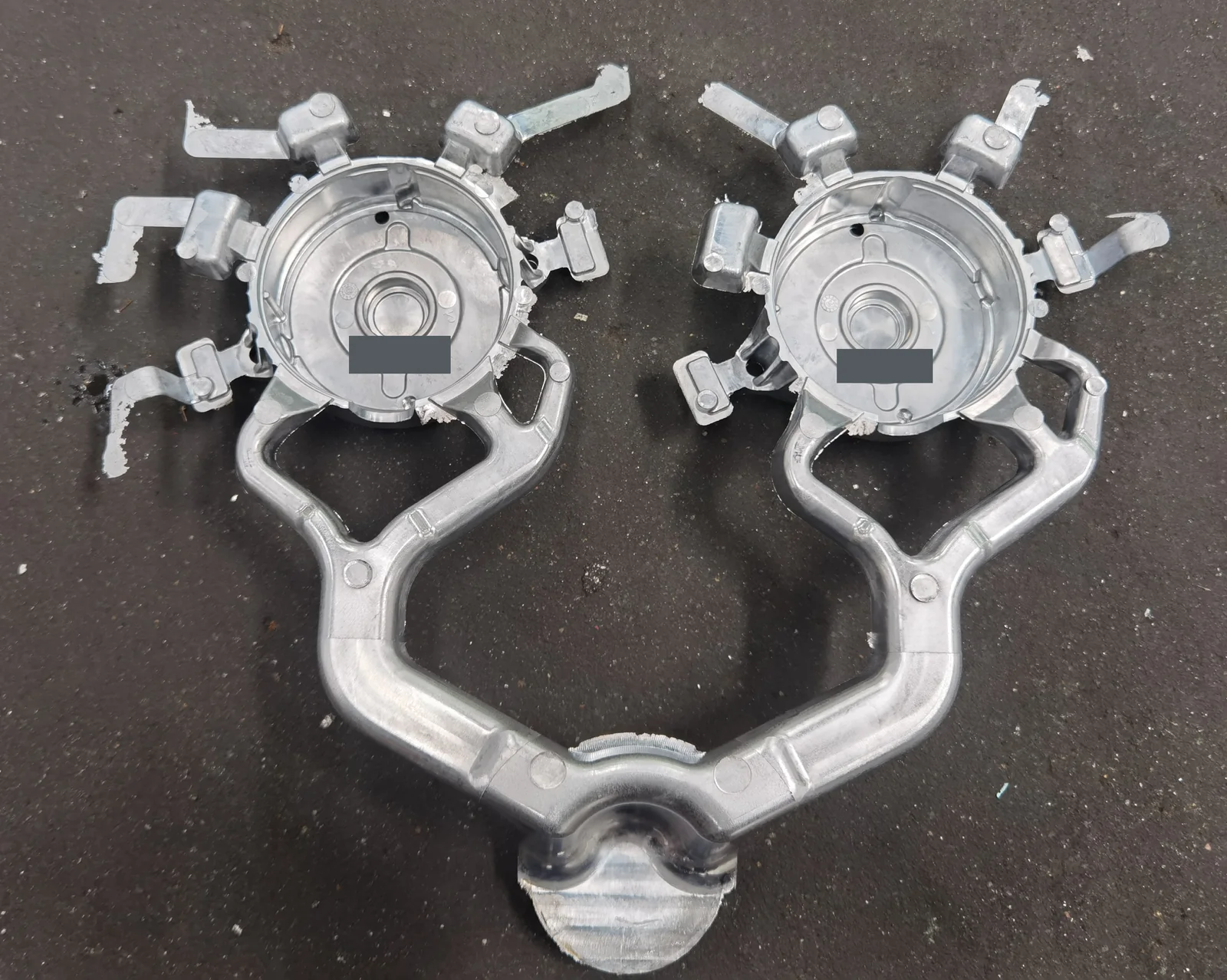
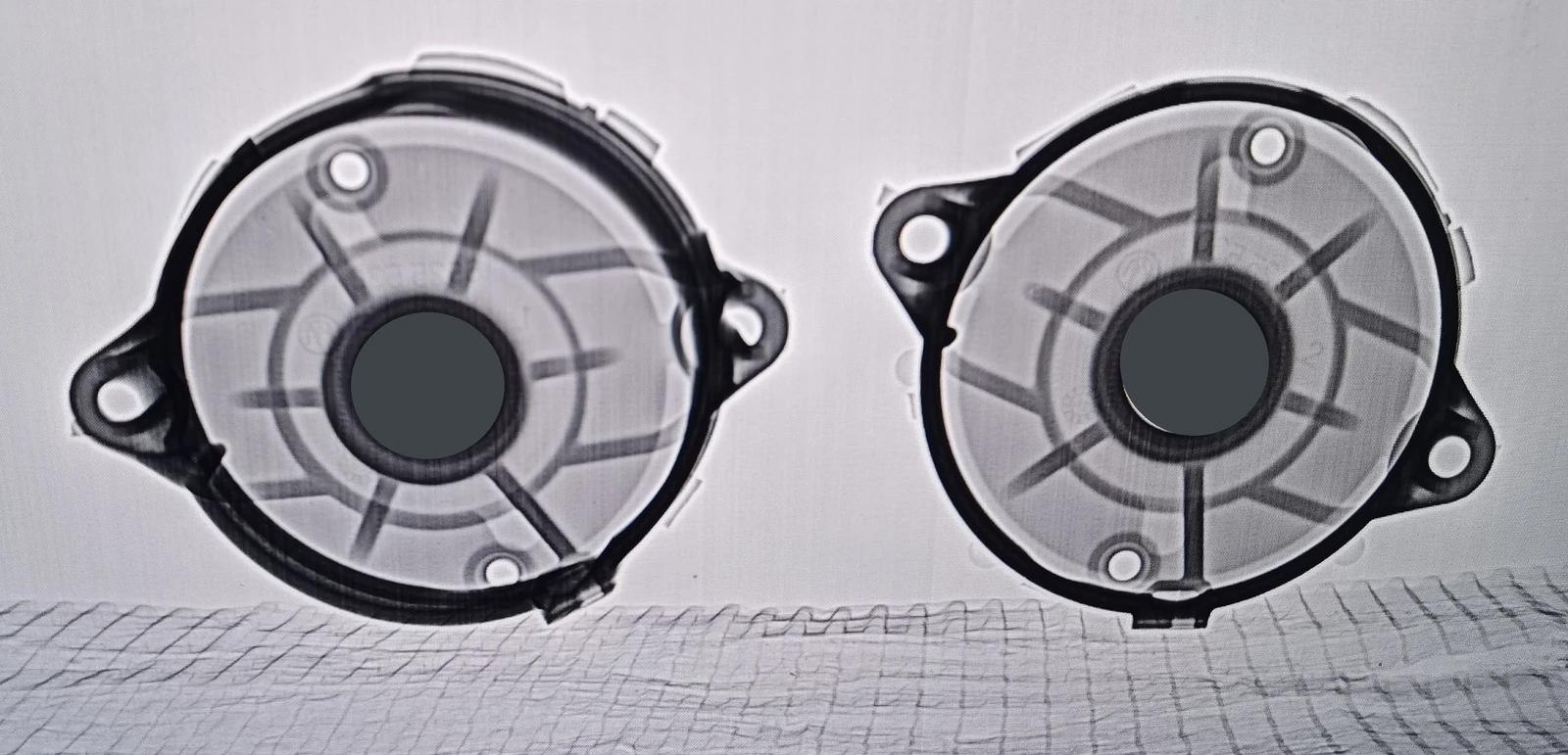
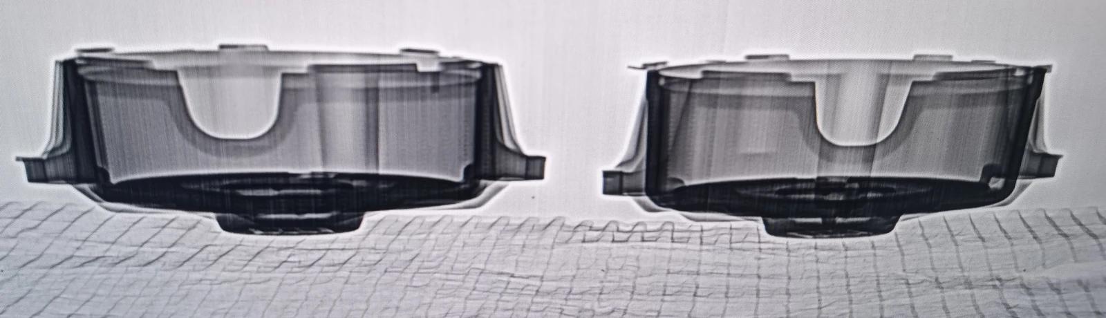
The images show the observations. Pore counts, pore sizes and compliance with the customer’s limits require a corresponding quantitative inspection result.
The project stage shown
Tool inspection and T0 trial records provide a basis for further technical review.
This case shows work from mold-base measurements, fits and assembly checks to T0 temperature and internal sample observations. Maintenance instructions accompany the project, covering installation and cooling connections, preheating, removal of aluminium residue from parting surfaces, and periodic insert and core-pin upkeep.
This case focuses on engineering records from tool inspection and the T0 trial stage.
START YOUR TOOLING PROJECT
Start with the drawing and quality requirements.
Share the part drawing, critical dimensions and tolerances, and quality requirements such as porosity limits to discuss your tool development and manufacturing needs.